Vingegaard Makes History as a 3x Grand Tour Winner
The Rest is Written
Vingegaard Makes History as a 3x Grand Tour Winner
Ready For The Break
Animate the race. Sprint early. Dive into corners. Soloist does it all.
All Juice, Less Squeeze
Rouvida delivers power and range.
The Original Go-Fast Gravel Bike
All-day speed, all-day comfort.
Team Visma | Lease a Bike
Team Visma | Lease a Bike (formerly Team Jumbo-Visma) first threw a leg over their Cervélo bikes in 2021, and started stacking up historic wins immediately. They've kept going, and in 2023 achieved the unprecedented—winning all three Grand Tours in a single season.
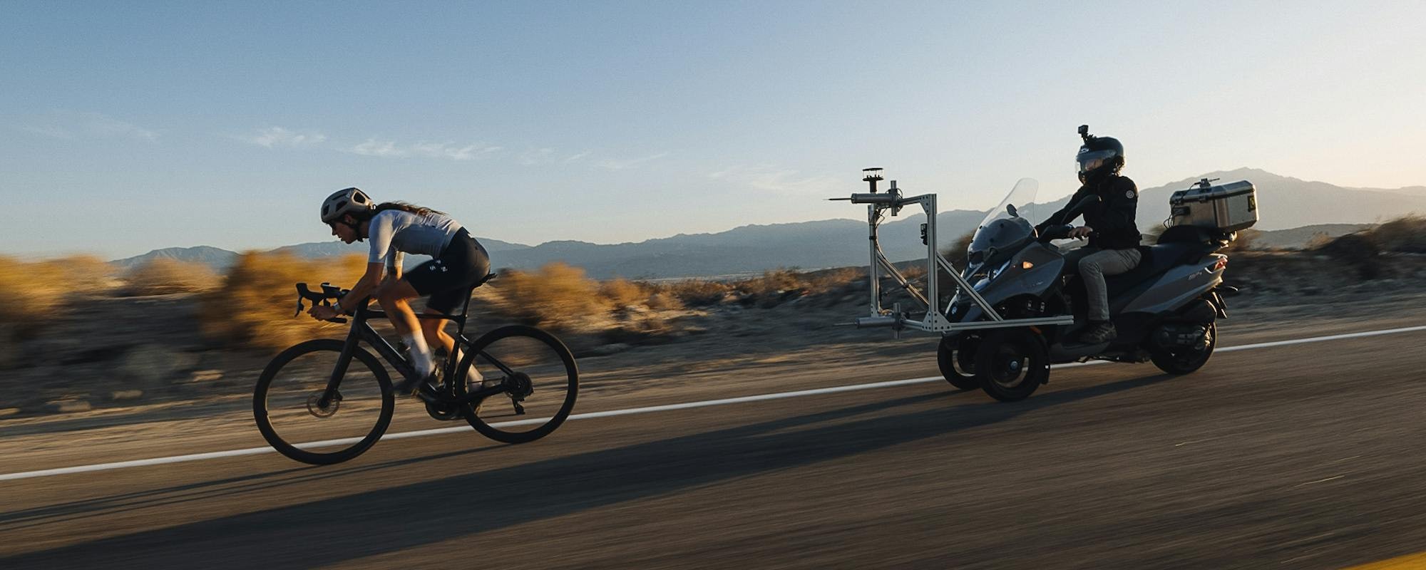
MAKE FRIENDS WITH THE WIND
You can, in fact, reinvent the wheel. Meet Turbulent Aero, a unique R&D program that leverages real world wind data to create the most rapid, stable, and best handling wheels in real world riding conditions.
MAKE FRIENDS WITH THE WIND
You can, in fact, reinvent the wheel. Meet Turbulent Aero, a unique R&D program that leverages real world wind data to create the most rapid, stable, and best handling wheels in real world riding conditions.